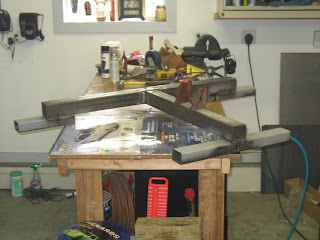
Not a lot of time on the rotisserie this weekend, but some visible progress. I was able to put together the first portions of the adjustible structure that the car hangs from (via the pivot). I was able to finish putting together the mounting points for the hyraulic ram as well. Some updated pictures below.
attaching the upper ram bracket was a little touchy. In the end - I think I would have moved the pin further out to get me more space, but I ended up making a small modificatino to the bracket to allow it to attach and center itself on the ram.
Here's a picture of the way things looked as I left them tonight. Some good progress overall. It all hangs square for the most part - which is comforting the time I've put in was worth it. The lower ram platform will need to be shortened (I cut it long in the first place) but that was the only issue I was able to find.
Sunday, April 17, 2011
Wednesday, April 13, 2011
A little more progress- Rotisserie Upgrights
Below is a picture of the mocked up rotisserie base mounted to the upright tube and riser. I have the vertical adjutment safety pin holes set about every three inches from 0 to 15 (knowing that my ram has 18 inches of overall travel).
Note the base for the jack - after a few cocktails, Shane and I figured this would be as good a way as any to support the jack. The plan is to build that platform into the gusseting structure to support the rotisserie down the center plane (versus right to left of the rotating axis).
Here's a fuzzy shot with the ram in place.
The plan is to continue that piece of square tubing down to the bottom rail to complete the structure. The last thing we did was use the hole saw to cut a pice that would attach to the outer collar on the rotating pin. This would provide an anchor point for the top/movable portion of the ram.
Below is a little closer perspective of that piece sitting on top of the ram. Tonight I drilled a hole in it to run the pin.... mis-marked it, so I had to weld it closed and re-drill. An eighth of an inch is a lot on a small piece like that. Also in the pic below you can see a little closer where I have the pins set up to safety lock things into place.
More to come.
Tuesday, April 12, 2011
On to the ROTISSERIE
I've received a lot of feedback from peers at work and others who give me this confused look when I say that I'm going to build a rotisserie for my Mustang so I can really work on every nook and cranny it has to offer.
Well its true - and all that steel I purchased well over a year ago is going to go to some good use.
First off - after perusing the internet and looking for just the right plan that I thought would be robust enough to carry just about anything and be manageable for me to put togehter with a chop saw and welder... I came across this design :
http://www.harwoodperformance.bizland.com/1941buick/index.html
http://www.harwoodperformance.bizland.com/1941buick/Rotisserie(rev.2).pdf
There were a lot of things I liked about how this appears to go together.. and it had a materials list which I've stuck to about 80%... You'll see the differences later.
First things first... The steel. I purchased it from State Steel- here in Des Moines. They were pretty good to work with overall, but the one thing I would mention is that the steel comes in long lengths. To cut it warrants a 10-15 dollar fee for each cut. When I purcahsed my first load I opted to cut it with a HACKSAW myself, and it was a huge pain. Guys in the warehouse actually had bets on how long it would take me to get through all the material. Let's just say I did it faster than most said I could... especially driving a minivan with plates that say SNKMPIE.
Lesson learned- take a trailer that can handle long lengths... or just pay the man.
Second-
Cut the long lengths into each of the pieces needed for the rotisserie. My recommendation here is to try to cut the larger pieces first... then wait on some of the smaller gussets/details... as I've changed mine up a little as I've went along. But - mostly - especially with the bases, I've been very close to the plan.
Third -
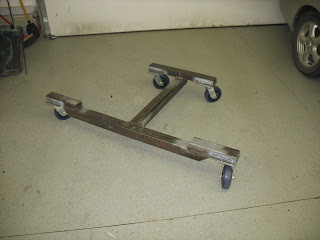
The bases. Here are some shots of the bases. One with casters (from Harbor Freight - about $13 a piece when maxing out the discount) and one without.
Note the 45 degree cuts on the inside of the wheels closest to the cam. What I found was the wheels when rotating came into contact with the frame.
I found that the 2x3 rectangle tubing didn't exactly accommodate my casters... so I had to expand the footprint with some angle steel. See below
Well its true - and all that steel I purchased well over a year ago is going to go to some good use.
http://www.harwoodperformance.bizland.com/1941buick/index.html
http://www.harwoodperformance.bizland.com/1941buick/Rotisserie(rev.2).pdf
There were a lot of things I liked about how this appears to go together.. and it had a materials list which I've stuck to about 80%... You'll see the differences later.
First things first... The steel. I purchased it from State Steel- here in Des Moines. They were pretty good to work with overall, but the one thing I would mention is that the steel comes in long lengths. To cut it warrants a 10-15 dollar fee for each cut. When I purcahsed my first load I opted to cut it with a HACKSAW myself, and it was a huge pain. Guys in the warehouse actually had bets on how long it would take me to get through all the material. Let's just say I did it faster than most said I could... especially driving a minivan with plates that say SNKMPIE.
Lesson learned- take a trailer that can handle long lengths... or just pay the man.
Second-
Cut the long lengths into each of the pieces needed for the rotisserie. My recommendation here is to try to cut the larger pieces first... then wait on some of the smaller gussets/details... as I've changed mine up a little as I've went along. But - mostly - especially with the bases, I've been very close to the plan.
Third -
The bases. Here are some shots of the bases. One with casters (from Harbor Freight - about $13 a piece when maxing out the discount) and one without.
Here's one with casters - on the floor.
Note the 45 degree cuts on the inside of the wheels closest to the cam. What I found was the wheels when rotating came into contact with the frame.
I found that the 2x3 rectangle tubing didn't exactly accommodate my casters... so I had to expand the footprint with some angle steel. See below
Here's the finished product.
I really liked how these allowed me to really dial in the welder and see how much penetration things would take. In the end - the holes lined right up.
Once the bases were constructed it was time to figure out how to accommodate the upright sections on the rotisserie. In the original design, the vertical adjustability is handled at the end of the pivot point where a 2 inch section of square tubing is capable of being pinned in multiple locations to adjust the height. Honestly - this probably would have done a fine job for me as well, but I've seen other rotisserie models on-line and elsewhere with some vertical travel controlled as well by a hydraulic cylinder. I really liked the idea, so I invested in two 8 ton cylinders and a 24 foot stick of 3.5 inch square tube to sheath the already cut 3 inch tube.
Here's a shot of the cylinder - think two 8 ton rams is enough? Yeah. Me too.
Above/Below - here are two shots of the construction of the rotating pin assemblies. These consist of a one piece of 3.5 inch .375 wall DOM tubing and a two foot piece of 2.75 OD .25 ID DOM tube.
I bought these from http://www.onlinemetals.com/.
Trouble with these pieces I found...was that the math would indicate that these should fit inside one another. Unfrotunately, that wasn't the case at all. I spent three nights grinding, sanding, smoothing, and finishing the work on the inside tube on my pal Shane's belt sander so that it would fit inside the outer. SO glad that is done. Next time I'll hedge a 16th of an inch to get the pieces to fit together.
At this point - I've been having a lot of fun working with the HTP welder. The unit has been great up to this point, and after about a year I had a couple things that caused me some issue. One call to HTP, and they had two new parts to me free of charge and things have been great since. The great thing about welding thicker material - is that its more forgiving. With some practice, welds definitely improve.
Oh - and weld-though primer. That stuff is worth the money as well.
Next up - drilling holes in the rotating pin. Plus fitting the hydraulic cylinders. Beginning the home stretch.
Fixing The Taurus
After an entire winter of not having instrument cluster lights on my Taurus, I decided it was time to change that and dig in ... finally fixing the problem which was a bad electrical connection, likely caused by the cold.
It requires some work to get the dash apart - but this was workable with a socket set, a screwdriver, and a special tool from O'Reiley's that removes the Ford radio.
In the end I had to have the drums turned, and replaced hardware, shoes, and wheel cylinders. While I was at it, I ended up getting some wild hair and decided to paint the drums. I kind of like it... even if its on a 2002 Ford Taurus.
Here's the exposed drum with all the internals installed.
It requires some work to get the dash apart - but this was workable with a socket set, a screwdriver, and a special tool from O'Reiley's that removes the Ford radio.
Here's a shot of the dash mostly taken apart. The hardest part was getting the radio out. Once it was out, all that was needed was removing the fasteners behind the radio, removing similar fasteners holding the plastic panel beneath the steering wheel in place, and then popping the plastic pieces out.
Lastly the instrument cluster comes loose and the electrical connection is actually made on a thin plastic circuit sheet that runs the juice to all the spots (including lights) inside the cluster. I cleaned the contact points with alcohol and a couple QTips, checked the lights... they worked...and put it all back together.
I should have done this months ago.
And.. Brakes
The other thing that I had to resolve on the Taurus was this strange squealing noise coming from the rear brakes. After some closer inspection with Dad, we discovered that the springs in the passenger rear assembly had rusted through and were tumbling inside the drum.
In the end I had to have the drums turned, and replaced hardware, shoes, and wheel cylinders. While I was at it, I ended up getting some wild hair and decided to paint the drums. I kind of like it... even if its on a 2002 Ford Taurus.
Here's the exposed drum with all the internals installed.
For some reason I didnt' take pictures of the car with the wheels on. I'll update this with some pictures when I have them.
Subscribe to:
Comments (Atom)


